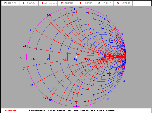

To locate the load impedance on the s.w.r. Remember, we are starting at the generator end of the transmission line. Now draw a radial line from prime center through this plotted point to the wavelengths scale, and read a reference value, which is 0.195 (at B), on the TOWARD-LOAD scale. circle through the point, and transfer the radius to the external scales. Normalize the input impedance with respect to 50 ohms, which comes out 1.4 - j0.5, and plot this value on the Chart. We desire to determine the actual antenna impedance. The line is 2.35 wavelengths long, and is terminated in an antenna. In this type of problem, the measured impedance is plotted on the Chart, and the TOWARD-LOAD wavelengths scale is used in conjunction with the electrical line length to determine the actual antenna impedance.įor example, assume we have a measured input impedance to a 50-ohm line of 70 - j25 ohms. The input or generator end of the line would be that end connected to the device for measurement of the impedance. Whether the antenna is intended purely for transmission of energy, or purely for reception makes no difference the antenna is still the terminating or load impedance on the line as far as these measurements are concerned. In this case, the antenna is connected to the far end of the line and becomes the load for the line. The electrical length of the feed line must be known, and the impedance value at the input end of the line must be determined through measurement. To determine an actual antenna impedance from the Smith Chart, the procedure is similar. Home - Techniek - Electronica - Radiotechniek - Radio amateur bladen - QST - Smith-chart calculations for the radio amateur 2


 0 kommentar(er)
